Water Source Heat Pumps

Models:
(2,5- 43 kW)
Water Source or Ground Source Heat Pumps
Horizontal, Vertical, Console or Split Models
- Environmentally friendly R410A refrigerant
- High EER and COP values
- 3 steps fan speed control
- Washable filter
- Acoustic package
- Drain pan overflow control system
- Corrosion resistant drain pan
- Outdoor panels are coated with galvanized aluminium
- Outdoor panels are coated with polyurethane painting
- Hanging brackets
- Valve kit (Balancing valve, selenoid valve, strainer, flexible hoses)
- 15m communication cable between the unit and thermostat
- Openration mode selectable based on return air or ambient air temperature sensor on the thermostat
Distinctive Features
One of the most outstanding feature of ATLANTIK water source heat pumps is three speed fan control. Fan speed can be
adjusted automatically with respect to cooling or heating request of the served area based on the information received through the thermostat.
19 error codes can be monitored on thermostat. The refore it is easy to determine what type of error occured in the unit. Most of problems are solved with the help of our authorized technicians by phone and the after sales cost of the user is
reduced.
ATLANTIK water source heat pumps have an oven painted surface with high corrosion resistance and provides a nice
and stylish apperance in open ceiling applications. The units have 2 pieces polyurethane (washable) filters.
Thanks to the simple connections construction they can be easily removed.
Thanks to the flange located at the inlet side, duct connections can be made easily.
Electronic fabricated phase protection relay is provided as standard.
15-20m long two-pin plug thermostat cable is standard for each unit.
Units can be programmable weekly, daily and hourly thermostat controller
Black color design that completes the visual in open celling applications


ATLANTIK water source heat pump units have 4 sensors. The water temperature sensor is located at the condenser inlet and indicates the temperature of the entering water. The evaporation (refrigerant) temperature can be measured with the sensor located on the surface of the coil. The return air temperature can be read by another sensor located behind the filter in evaporator.
Also, in non-return flow applications, tho room temperature can be measured via the sensor on the thermostat. Additionally, a freze protection sensor is located on the condenser line. (The sensors are shown in the above diagram) There is also e freezing switch on the condenser (heat exchanger) line. This switch activates the device to protect against possible heat exchanger freezing
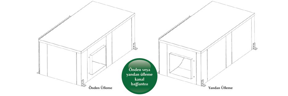
ATLANTIK water source heat pump units can blow from the front (long edge) or from the side ( short edge) to suit the needs of the installation.
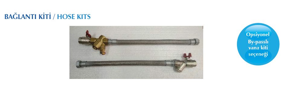
The valve kit in ATLANTIK water source heat pumps can be optionally standard or with by-pass. The water side connection kits for EWH models consist of 2 ball valves, 1 strainer, 2 stainless steel braided flexes, 1 motorized valve, 1 dynamic type balancing valve and sufficient number of intermediate connection elements. A set of connection kits has two parts for outbound and return, and each set is delivered in a special packaging box.
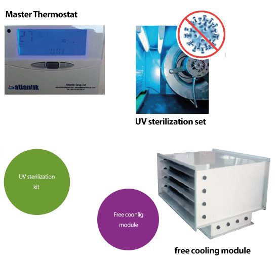
- Economizer For Free Cooling
- Electical Heater
- Balance valve kit
- Programmable thermostat
- BMS Communication Card (Modbus or BTL certified BACNET)
- UVC lamp
- Master Thermostat
| Model | EWH03H | EWH04H | EWH07H | EWH010H | EWH13H | EWH15H | EWH22H | EWH30H | EWH045H | ||
| Cooler Liquid | R410A | ||||||||||
| Power Supply | V/Ph/Hz | 220V-240~/50HZ | 380V-415/3N~/50Hz | ||||||||
| Cooling Capacity Net | Kw | 2.50 | 4,10 | 7,40 | 10,56 | 12,50 | 15,88 | 22,00 | 30,00 | 43,00 | |
| Sensible Capacity | Kw | 1,80 | 3,08 | 5,46 | 8,65 | 9,38 | 11,02 | 16,50 | 22,50 | 32,40 | |
| Heating Capacity Net | Kw | 2,90 | 5.25 | 8,50 | 11,96 | 16,05 | 20,90 | 29,00 | 38,50 | 58,00 | |
Power Absorbed in Cooling |
Kw | 0,54 | 1,02 | 1,76 | 2,23 | 2,78 | 3,87 | 5,30 | 7,14 | 9,55 | |
| Power Absorbed in Heating | Kw | 0,60 | 1,09 | 1,77 | 2,21 | 2,85 | 4,22 | 5,60 | 7,95 | 9,55 | |
| EER | 4,63 | 4,02 | 4,20 | 4,74 | 4,50 | 4,10 | 4,15 | 4,20 | 4,50 | ||
| COP | 4,83 | 4,82 | 4,80 | 5,41 | 5,63 | 4,95 | 5,18 | 4,84 | 4,79 | ||
| Current Drawn in Cooling | A | 2,50 | 4,73 | 8,16 | 10,34 | 12,89 | 6,66 | 9,13 | 12,29 | 16,44 | |
| Current Drawn in Heating | A | 2,78 | 5,60 | 8,21 | 10,25 | 13,22 | 7,27 | 9,64 | 13,69 | 20,83 | |
| Air Flow | m3/h | 450 | 800 | 1260 | 2030 | 2340 | 2650 | 4300 | 4900 | 8000 | |
| External Static Pressure | Pa | 20 (0~40) | 60 (0~100) | 80 (30~100) | 80 (60~120) | 120 (80~150) | 120 (100~200) | 150 (100~200) | |||
Water Flow |
m3/h | 0,54 | 0,88 | 1,59 | 2,27 | 2,69 | 3,41 | 4,73 | 6,45 | 9,25 | |
| Water Side Pressure Loss | Kpa(mSS) | 12(1,2) | 29(2,9) | 25(2,5) | 43.8(4,38) | 33.7(3,37) | 43(4,30) | 60(6,0) | 42(4,2) | 85(8,5) | |
| Water Connection | İnch | Rc3/4″ | R1-1/4″ | ||||||||
| Volume | dB(A) | 35/33/31 | 41/37/36 | 49/45/42 | 49/46/43 | 55/52/49 | 55/52/49 | 58/55/52 | 59/56/53 | 62 | |
| Dimensions(ExBxY) | mm | 487 *800*350 | 543*830*382 | 604*1024*490 | 736*1124*510 | 756*1313*512 | 988*1378*592 | 1085*2040*592 | 1114*2059*737 | ||
| Compressor Type | Rotary | Scroll | |||||||||
| Water Side Heat Exchanger | Koaksiyel | ||||||||||
| Net weight | Kg | 40 | 61 | 92 | 110 | 130 | 153 | 190 | 312 | 380 | |
NOTES:
1-In 60(0-120) ’60’ nominal static, which shows non-device static feature, soldier safety, (0-120) show the static stress given.
2-The cooling capacity is net and the inlet air is taken as 270C DB, 19 0C YT and the water entry date is 30-350C.
3- While calculating the heating, inlet air is taken as 20 inlet ⁰C KT, 15 ⁰C YT and water as 20 ⁰C.
In 4-EWHH-EWH30H models, the fan is fast and the air flow above is high, the static velocity is earthquake.
5- The water flow rates in the table are based on the 5 ⁰C delta T temperature in the cooling operation.
6- The balancing valves in the valve kits supplied with the heat pumps are adjusted according to the nominal water flow rates in the table. Balancing valves can also be supplied specifically for different water flow rates.
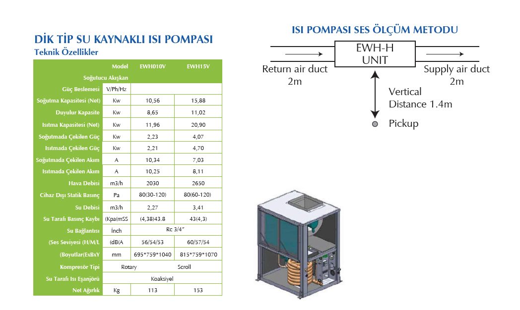
7-The values in the table are sound pressure at a distance of 1.4m from the device according to GB/T7725-2016, GB/T188-2017, GB/T6882-2016, JB-T4330-1999 standards.
8- We reserve the right to give the product, its design and price without notice.
| Air Side (0C) | Cooling | Heating |
| Minimum Return Air Temperature -KT1,2 | 16 | 15 |
| Nominal Return Air Temperature KT/YT | 27/19 | 20/15 |
| Makximum Return Air Temperature-KT/YT1,2 | 32/23 | 27/- |
| Water Side (0C) | Cooling | Heating |
| Minimum Water İnlet Temperature-KT1,2 | 10 | 10 |
| Nominal Minimum Water İnlet Temperature-KT/YT | 30 | 20 |
| Makximum Water İnlet Temperature-KT/YT1,2 | 50 | 40 |